Tuesday, October 19, 2010

Linear pipe


Use the following AUTOCAD command:
1. circle
2. offset
3. extrude
4. line
5. subtract

Method:

1.Draw a circle with the radius value of 50mm whereas the thickness value is about 5mm offset.


2.Switch the current view into SW isometric then create a straight line about 400mm directly to the center point of a circle.


3.To begin the extrusion of an object enter the command extrude then select the two circle followed by typing the word Path. Currently select the line or what we called the extrusion path then press the enter key to see the result.


4.Use shade command to hide from view of isoline.


5.Take away the unnecessary objects. Use the command subtract:


6. then press ENTER.

7. select solids and regions to subtract.


8. Finally press the key ENTER


RESULT

Monday, October 18, 2010

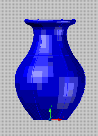
3D flower base


Use the following AUTOCAD command:

1.line
2.spline
3.revolve

Method:

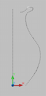
1.Change the current viewport into “front view”.


2.Begin command “line” with the height value of 30cm, after that create a plain sketch using command “spline” to provide a simple design needed to form a solid object.


3. command “revolve” to create a 3d solid object.


Sunday, October 17, 2010

Studio room with 3D roof plan


Use the following AUTOCAD Command:
1. rectangle
2. 3dface

Method:

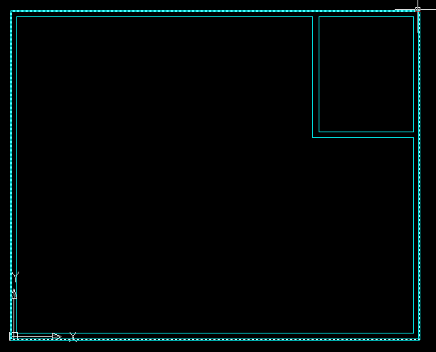
1. Create a rectangular roof plan by using command “Rectang”. Make a partition structure suitable to the desired roof plan.


2. Switch the current viewport into the SW isometric and start to command “3Dface.”


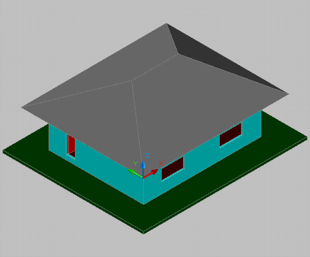
3. Here is the result after pointing towards the given point. By using the command “3dface” followed by “.xy” then click to “first point” after that is require to specify the "value" of a given "height". Repeat the same procedures depend upon the particular point.


4. Now, here is the simple outcome..

Friday, October 15, 2010

3D studio room


Use the following AUTOCAD command:
1. pedit
2. extrude
3. subtract

Method:

1. use "pedit"command to convert multiple objects into one object.


2. switch the current viewport into SW isometric.


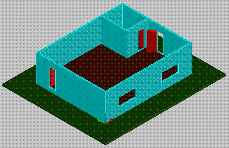
3. command "extrude" to switch the flatted wall into 3d solid wall drawing.


4. enter the "shade" command into the command entry to look more realistic than to unshaded mode. Followed by subtracting the 3d wall by means of using command "subtract".


5. place some drawing object to the respective location to become more attractive and also in good looking, such as floor, door and window laying.

Wednesday, October 13, 2010

"how to create a simple Floor Plan "

Create a "10x8 meters" flexible Studio Room


Use the following Autocad Command:
1. Layer
2. Rectangle
3. Offset
4. Trim
5. fillet
6. mtext

Method:
1. Start from the scratch
2. Create a new Layer
3.Use command RECTANG to create a 10x8 meters rectangular shape studio room. Subsequently, use command offset with the thickness value of 0.15 meters to create a wall plan.

4. Repeat command RECTANG, reason is to create a 2.5x3 meters comfort room. Also assign door and window details to the prospective location.

5. 1.5 x 3 meters is the size area of the counter. Command Fillet is need to create a clean round corner of the counter with the 0.5 meters radius value.Put some text details inside the studio by using command mtext. Finally, go to Dimension Menu and use linear for dimensioning the area of studio room.